
Bus systems for fail-safe networking: Safety versus availability
Contents
• Standard networking
• Basic principles of safety buses
• Network structure for safety bus systems
• Prognosis
Standard networking
Automation systems of the past few years have been characterised by major changes. Today, PLC has established itself for controlling operative procedures as has decentralisation in the use of conventional field bus systems. A hierarchical structure of operative field buses, which assigns the suitable bus system to the requirements of the respective level, is becoming increasingly important, particularly in larger plants or factories (see Fig. 1).

The good experience gathered in networking in the operative area of plant controlling, with all the benefits regarding reduced wiring requirements, comprehensive diagnostic possibilities or increased flexibility, is currently being expressed in the desire to network the manifold safety functions of a plant. Obviously the established standard field busses are not always suitable against the backdrop of safety. Therefore the field bus spectrum has been expanded by adding a safe bus system.
Safety-orientated networking
The detailed hierarchical structure of networking operative functions is also dependent on the industry concerned. For instance, the demands made upon sensors and actuators in networking bus systems in the processing or process industries are different to those in the field of building automation. In the following, attention will be concentrated mainly on the immediate environment of manufacturing automation.
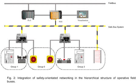
Here, safety functions are usually realised either conventionally using a multitude of safety switching devices, or by employing a so called programmable safety system (PSS). By coupling to the operative field bus, the desire to make information available to the operative control system about the status in the safety-orientated part of the plant can be satisfied. Both functions, operative and safety-orientated control systems, are realised independently of one another and are only coupled together to exchange data. A separate safety-orientated network will be necessary if a defined assignment of responsibility for safety-orientated areas is required, if transparency and speed demands require it, or if the safety-orientated section of a plant is to be run independently of the operative section. This path is also chosen in the introduction of safety-orientated networking (see Fig. 2). There are clear reasons for a safety-orientated network separate from the standard field bus: Under the heavy strain endured by machines or plants today, downtimes can be critical. The probability that a fault in the operative section of the control system will also affect the safety section if both are integrated on one bus line is high. As a result, such a fault in the standard part would bring the entire plant, or large parts of it, to a standstill via the safety function, without this being necessary for the safety of the machinery. Apart from the fact that it is difficult to locate the original fault from the maintenance and servicing side, the integrated solution, in which standard and safety data are integrated on one bus system, will lead to more frequent and longer machine or plant downtimes. The increased difficulty involved in fault location is a consequence of mixing responsibilities.
Without a doubt, the joint operation of standard and safety bus systems also results in their being subjected to increased strain. But because definite requirements regarding specific reaction times exist particularly in the safety area, the data rate will have to be raised in mixed systems as a matter of necessity. This results in an increase in expenditure for devices and cabling, as well as for EMC measures. Irrespective of this, the increased risk of mixed system downtimes remains. Against this background, the extra expenditure for laying a second bus cable for the safety section of one machine or plant is negligible in the majority of cases.
In the following description, only the safety-orientated part will be looked at. Three basic forms of safety-orientated networking are here of interest from the user's point of view (see Fig. 3).
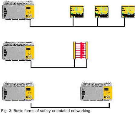
In the first case, a safety-orientated control system networks decentral input/output modules. The safety-orientated sensors and actuators, such as conventional commercial emergency on/off switches, safety gate switches or contacts, are connected locally using input/output modules. This form corresponds to the pure decentralisation of the familiar PSS programmable safety control system.
By disclosing the safety-orientated bus system, a wide range of manufacturers can be developed offering field modules with direct connections to the safety-orientated bus. The operator not only profits from the savings in wiring expenditure and effort, he also benefits much more from the simple and convenient assignment of parameters via the safety-orientated bus. This advantage becomes greater the more complex the respective field module is (e.g. light grids, scanners, drive units or valves). For example, if plants are located far apart from one another, it may be necessary to couple separately networked plant sections on a safety-orientated basis. An example of this are press lines, which are normally each fitted with their own one safety control system for each individual press, but where the individual systems can exchange safety-orientated data.
Return to Table of Contents
Basic principles of safety buses
Transmission errors
Standard field buses are not always suited to transferring safety-orientated data. When the plant is to be classified according to Category 4 in line with EN 954-1 or AK6 according to DIN 19250, then it is time for the safety-orientated bus system to be put to more intensive use.
From the economical standpoint, redundant construction of the transfer medium does not normally come into question. On the one hand, the required degree of safety must be provided by the bus protocol and network management, and on the other the hardware components must be designed with safety in mind.
The initial consideration is that errors are to be avoided with a view to availability, and they must be detected and controlled from the safety point of view.
Different measures must be taken to detect and control the various transmission errors (see Fig. 5).
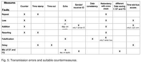
Expressed simply, a bus system is selected which per se (until and including Layer 2) has low error rates and has perhaps already implemented some error detection and correction measures, and which is then expanded to higher layers (user layer 7) with the corresponding measures. An important standpoint here is that the error detection and correction measures are safe in the sense that there is a dwindling probability of their failing.
Temporal behaviour
Explicit requirements regarding the absolute temporal behaviour of a safety-orientated bus do not exist. Comparisons with conventional systems serve as a benchmark, which must not reflect unfavourably on safety-orientated networking.
However, from the user's side concrete situations produce concrete demands: a light grid for safeguarding a press must function with the minimum amount of spatial requirements to avoid increasing the size of the plant unnecessarily. In other words: minimum reaction times are needed.
In principle, a distinction must be made between reaction times and error detection times; the former describes — taking the simple case of digital input/outputs — the period of time which passes between emitting the input signal until switching of the corresponding output signal. Sensor and actuator switch times are not taken into consideration. The error reaction time is to be understood as the max. period of time which passes until an error in the safety bus system has been detected and the transition to a safe condition.
Obviously, these times do not just vary according to the basic principle selected for the safety bus, rather they are influenced by the respective application. In all cases, it must be ensured that times which have been projected and stored are adhered to, or if they are exceeded, that a safe condition is restored.
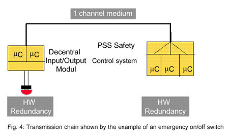
This temporal behaviour is described in more detail taking the example of the event-orientated. Here an emergency on/off signal is transferred via a decentral input/output module to the PSS safety control system and goes from there to the appropriate actuator (see Fig. 6).
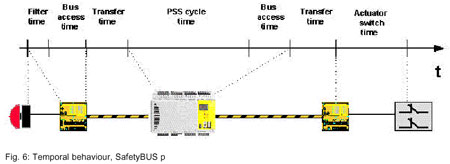
The bus access times and transfer times are heavily dependent on the bus procedure being used. In event-orientated systems such as SafetyBUS p these times are generally short, particularly when different message priorities are implemented. On the other hand, a high bus usage can also lead to longer access times even for higher-priority messages. For this reason, plant-specific projected reaction times must be safely adhered to. This applies especially in the case of possible expansion of the plant.
Return to Table of Contents
Network structure for safety bus systems
Substructures
The topology of the selected safety bus must also correspond to the plant, i.e. the structure of the bus system must be able to simply and comfortably network the different safety-orientated actuators and sensors. This also applies to the subject of the availability of field modules with direct connections to the safety bus, or decentral input/output modules with a suitable I/O configuration and design.
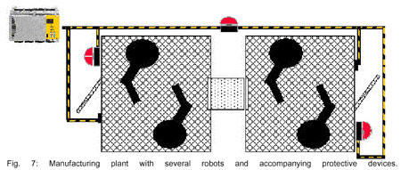
As far as the safety aspects are concerned, larger plants especially are often divided into individual part sections, whose safety fittings on the one hand are supposed to react to the plant section more-or-less self-sufficiently, while on the other hand having an influence on the plant as a whole. An example of this is a manufacturing process consisting of several robots. Safety gates are primarily supposed to relate locally to the respective robots, while an emergency on/off switch must be effective throughout the entire plant. For economic reasons, however, only networking with one safety-orientated bus system will generally come into question (Fig. 7).
At first glance, this consequently means that an error at a local safety device leads to the entire plant being shut down. A similar thing happens if maintenance work (e.g. changing tools on a robot) has to be carried out at another section of the plant.
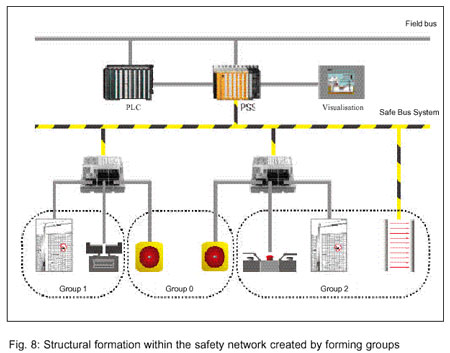
The solution to the problem is the introduction of groups within the safety-orientated bus. Each subscriber in the safety-orientated network can be allocated a group number. If a fault occurs, only the affected group is safely deactivated, the rest of the bus system continues functioning. This method of forming groups goes a long way to reaching the objective of attaining the highest possible availability for the machine or the plant. At the lowest level, an established standard bus system equipped with fault detection and repeat mechanisms helps to keep availability at a high level. The topology of the distinction between safety and standard serves the same objective on the highest abstract level.
The introduction of different groups is the prerequisite for the economically justifiable formation of substructures within the safety-orientated bus system. The example shown above places further demands on the modules and/or subscribers: if emergency on/off switches, protective gate switches etc. are integrated in the safety bus via decentral input/output modules, these modules must be able to support at least two different groups. Otherwise protective devices from varying group configurations could not be connected using one module.
Return to Table of Contents
Prognosis
The decentralisation of operative control systems is fact. Definition of the safety-orientated bus system also creates the prerequisite for enabling the functional safety capabilities to profit from the far-reaching benefits of decentralisation.
Alongside the openness of a bus system which is only of theoretic value on some field buses, a club brings manufacturers and users together for the purpose of further development and standardisation. Thanks to a certified chip set the development of directly interfaced field devices has been made a great deal simpler. Based on the press working line described at the beginning, this means that in future not only are the individual safety controllers interconnected reliably (instead of today's hard wired I/O connection), but protection devices such as safety beam gates or press safety valves will be integrated directly in the bus network. On the other hand for economic reasons simple safety functions like the emergency shutdown push-button switch or safety door switch will still be connected to the safe bus system via reliable decentral I/O modules.
Return to Table of Contents
This article is provided courtesy of the ISA — the Instrumentation, Systems, and Automation Society.